
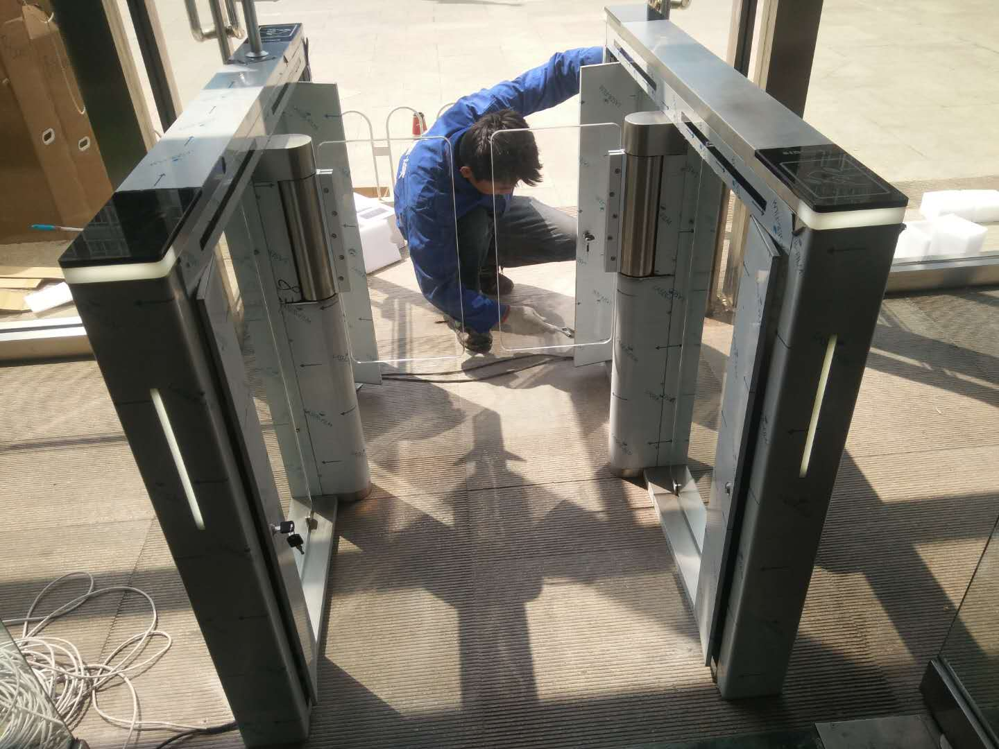
Complete Installation Guidelines for Pedestrian Turnstiles
As core intelligent access control equipment, pedestrian turnstiles (including flap barriers, swing gates, tripod turnstiles, etc.) are widely used in office buildings, industrial parks, supermarkets, stations and other scenarios. The installation of turnstiles involves mechanical fixing, strong and weak current wiring, and system commissioning. Standardized construction is essential to ensure stable operation, user safety and long service life of the equipment.
To help construction personnel and project managers achieve standardized installation and avoid hidden faults while complying with security and fire protection standards, this article sorts out the full-process standardized installation precautions for pedestrian turnstiles from four stages: pre-installation preparation, on-site construction, post-installation commissioning and acceptance, as well as safety and maintenance specifications.
1. Pre-installation: On-site Survey & Planning
Adequate on-site evaluation and reasonable planning before construction are the premise to avoid size mismatch, wiring errors and environmental adaptation failures. It is necessary to strictly control the site space, installation environment and wiring scheme.
1.1 Site & Space Planning
Accurately measure the width of the access passage, and reserve sufficient space for pedestrian passage and equipment maintenance according to the turnstile model. A maintenance space of at least 50cm shall be reserved behind the turnstile for later maintenance and troubleshooting. The ground flatness must be strictly checked with a height error within ±3mm. Uneven ground will cause equipment jitter, core wear and barrier jamming during operation.
For outdoor installation, a 10-20cm high cement platform shall be poured in advance to prevent equipment immersion by ponding. Meanwhile, a rain shelter shall be equipped, and moisture-proof and waterproof pretreatment shall be completed for the equipment to avoid short circuit and mechanical rust caused by humid environment.
1.2 Environmental Assessment
The turnstile shall be installed away from strong electromagnetic interference sources such as transformers and high-power motors, as well as areas with long-term strong light direct irradiation. Electromagnetic interference will cause abnormal signal and accidental opening/closing of the turnstile, while strong light will seriously affect the accuracy of face recognition equipment.
Confirm that the installation site is equipped with a stable independent 220V power supply and smooth network interface to ensure continuous and stable operation of the equipment.
1.3 Wiring Planning
Follow the strict separation principle of strong current and weak current with a wiring spacing of ≥30cm to prevent mutual signal interference and ensure stable transmission of access control and switch signals. Plan the laying path of PVC or metal line pipes in advance, and design waterproof bends for all line pipes to avoid rainwater backflow and cable corrosion.
2. On-site Installation: Standardized Construction & Detail Control
The construction stage determines the stability, safety and compliance of the equipment. Standardized operation shall be implemented in mechanical fixing, wiring, equipment docking, grounding and waterproofing to eliminate construction hidden dangers.
2.1 Mechanical Fixing Specifications
Fix the turnstile firmly on the ground with standard M10/M12 expansion bolts according to the base specification. Verify the levelness and alignment accuracy after installation: the body level error shall be ≤0.5°, and the parallelism error of multiple adjacent turnstiles shall be ≤1mm. Precise installation can effectively avoid operation jitter, barrier friction and abnormal mechanical noise.
Mechanical Mounting
2.2 Wiring & Connection Specifications
All cables shall be threaded into pipes without joints or twisting. The stripping length of cable insulating layer is controlled at about 5mm during wiring, and the wire ends shall be tightened or tinned to prevent virtual connection, looseness and short circuit.
Strong current and weak current must be routed in separate pipes (no shared pipes allowed). The RJ45 network crystal head shall be crimped firmly to ensure stable network signal transmission and avoid disconnection and recognition failure.
Turnstile Wiring Diagram
2.3 External Equipment Docking
Face recognition devices, card readers, exit buttons and other peripheral equipment shall be connected to the main board terminals in accordance with the official manual. The gate opening signal wire shall be connected to the NO/COM terminal for accurate signal matching.
The installation height of face recognition equipment is controlled at 1.2-1.5 meters, the optimal recognition height for human bodies. Keep the camera unobstructed and dust-free to ensure fast and accurate recognition.
2.4 Grounding & Waterproof Treatment
The turnstile main board and access control power supply must be reliably grounded with a grounding resistance ≤4Ω to prevent electric leakage and lightning damage. For outdoor equipment, seal the bottom gaps, pipeline interfaces and body seams completely to achieve all-round waterproof protection.
3. Post-installation: Commissioning & Acceptance
The equipment cannot be put into use directly after installation. It must pass power-on inspection, full function testing and linkage pressure testing to ensure compliance with safety and fire protection specifications.
3.1 Pre-power-on Safety Inspection
Keep the equipment powered off after installation. Fully inspect the wiring, terminal connection and pipeline laying to confirm no wrong connection, missing connection, short circuit or damaged cables. Power on the equipment only after all inspections are qualified.
3.2 Basic Function Testing
Test all authorization passage methods including card swiping and face recognition to verify smooth gate opening and closing, as well as normal response of indicator lights and voice prompts.
Face Recognition Verification
Focus on testing core safety functions: calibrate the infrared anti-pinch device to ensure the anti-pinch response time ≤0.2s to prevent clamping accidents. Test the manual push gate function after power failure to ensure free opening and closing, fully meeting fire evacuation standards.
3.3 System Linkage & Pressure Testing
Test the synchronous linkage of multiple turnstiles and the data synchronization accuracy between turnstiles and access control system to ensure real-time update of passage records and permission data. Simulate abnormal scenarios such as tailgating and retrograde passage to verify the normal triggering of alarm and interception functions.
Mainboard Terminal Definition
| SN | Terminal definition | Remark |
| 1 |
Power input |
Input |
| 2 | RS485 | Communication with Slave board |
| 3 | Infrared input | Input |
| 4 | Left pass infrared input | Input |
| 5 | Left anti-pinch infrared input | Input |
| 6 | Right anti-pinch infrared input | Input |
| 7 | Right pass infrared input | Input |
| 8 | Infrared input | Input |
| 9 | RS232 communication interface of LCD display | Communication |
| 10 | Open and fire alarm input
●BY-access controller open input ●XF-Fire alarm input ●L-OP-Left traffic open input ●COM-common teminal ●R-OP-Right traffic open input |
Input |
| 11 | Remote control | Input |
| 12 | Traffic light | |
| 13 | Speaker | Output
|
| 14 | Tri-color light strip | Output |
| 15 | Plug of brushless motor | Input and output |
| 16 | Motor hall | Input |
| 17 | Motor control | Output |
| 18 | Clutch | output |
Carry out long-term continuous passage pressure testing, observe the equipment operation status in real time, and eliminate hidden problems such as abnormal mechanical noise, excessive temperature rise and jamming to ensure long-term stable high-frequency operation.
4. Safety Operation & Daily Maintenance Specifications
Standardized operation and regular maintenance after installation are key to extending equipment service life, reducing failure rate and ensuring passage safety.
4.1 Safety Warning & On-site Standardization
Post obvious safety warning signs such as “Anti-pinch Warning” and “No Tailgating” around the equipment, and spray clear passage guide lines on the ground to standardize pedestrian passage and avoid man-made safety accidents.
Post obvious safety warning signs
4.2 Operation Safety Guidelines
All installation, inspection and maintenance operations must be carried out under complete power-off state. Live wire plugging and equipment disassembly are strictly prohibited. Do not open the equipment cover or touch internal mechanical and circuit components during operation to avoid equipment damage and personal injury.
4.3 Regular Maintenance
Regularly clean the face recognition camera, fill light and card sensing area to avoid recognition failure caused by dust blockage. Inspect cables and interfaces for aging and wear regularly and replace damaged parts in time. Lubricate the core transmission and rotating mechanical parts periodically to reduce wear and ensure long-term stable operation.
5. Summary
The installation of pedestrian turnstiles is a refined project integrating mechanical construction, circuit wiring and system commissioning. Standardized implementation of pre-planning, on-site construction, post-installation commissioning and daily maintenance can effectively ensure the safety, stability and durability of the equipment, meet national fire protection and access control industry standards, and provide reliable intelligent access management for various commercial and public scenarios.